
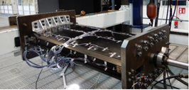
For CS2 OPTICOMS project, in September 2020, a 1.2m composite wing box, was successfully tested in Piaggio’s lab to check CIRA’s SHM algorithm capability to monitor bonding lines integrity through optical fiber.
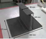
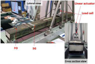
Structural Health Monitoring (SHM) system with optical fibers is an important part of OPTICOMS project, proposed in order to both verify the design during testing and to support load and bonding lines health monitoring “in service”, providing a tool to lower maintenance costs by means of individual maintenance approach. To reach this target, a building block approach is proposed through several specimens from element to component level. In particular: fig. (a) Spar bonded to skin coupon (2018), fig. (b) Beam channel specimen (2019), fig. (c) Small scale composite wing box (2020). In 2020 full scale composite wing will be tested at Piaggio lab. The small scale composite wing box testing was tested in Piaggio lab in September 2020 and documented in AIR-PAI-DEL (D-B-1.2-1) “SAT Optimized Composite Wing Small scale demonstrator test results” & AIR-CIRA-KO-B-1.2-3-A “SHM algorithm for bonding line flaws detection on small demonstrator”. The small scale composite wing box demonstrator was manufactured as part of OPTICOMS manufacturing tests, delivered to WIBOND consortium to be assembled (lower skin bonded to integral upper skin-spar structure), equipped by CIRA with optical fibers and finally tested during September 2020 at Piaggio lab under static loads. The demonstrator represents a cut out from the full-scale wing between BL 4100 and BL 5200: it consists of an integral structure made by upper skin and three co-cured spars that is bonded to pre-cured lower skin. Fiber optics sensors have been introduced inside the bond line in order to monitor this key structure element. Later second optical fiber is placed on top (inner) of the caps fig. (d) as well as several (~50) strain gauges.
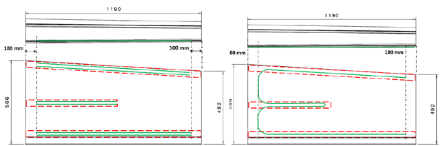
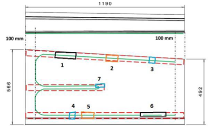
Two load cases were examined: compression and bending. Artificial damages were introduced to the demonstrator at key positions (mid beam run outs, over bond line), fig. (e). They have been designed to simulate several typical different bonding flaws in terms of sizing and positions. The challenge is the detection of damages smaller than the max allowed damage for the specimen under load condition lower than limit loads (a paradigm interpreted from certification guidelines) using the CIRA’s proprietary algorithm.
The analysis is first based on residual strains measurement (due to assembly, and installation), thus providing an estimation of damage at unloaded conditions. Later the demonstrator is analyzed under the predetermined and controlled load conditions. Quasi static measurements are taken and cross correlation of residual strains are made to estimate dames sizing and position in the same method. The compression test yields similar results to the unloaded state, the bending test detected the damages similarly to compression and unloaded states but under higher strain levels.
Main conclusion includes:
- The system (algorithm, sensor, process of installation) appears to be sensible at hundreds of micro strains signals.
- Unloaded configuration seems promising, to use in preliminary estimations.
- Compression test haven’t provided significant inputs over the unloaded case.
- Outer fibers remain mainly not contributing in all cases examined
- “Errors” that may be linked with singularity of the stricture at some points need to be further investigated.
- The approach at its current architecture is not fitting for “real time” in flight analysis, nonetheless, can be suitable for ground operation acting as a NDT (wing bending at self-weight with or without fuel), this philosophy should be further discussed.
- Maturity/robustness/ industrial level of the sensors as well as installation process should be further developed.
Future progresses will include: 1) further development of algorithm (“errors” analysis), 2) improvement of sensors installation and 3) conclusion on Vision towards integration in actual aircraft that may include certification authorities insight.
Stay tuned for the next updates.